
N10-009J 試験問題 1
次のどれが BGP を使用する最も適切な理由を表していますか?
正解: C
BGP (Border Gateway Protocol) is used for routing data between different ISPs, making it essential for the functioning of the internet. Its primary use is for exchanging routing information between autonomous systems, especially different ISPs. Preventing loops within a LAN is handled by protocols like Spanning Tree Protocol (STP), while improving reconvergence times and sharing routes with a Layer 3 switch are functions of other protocols or internal mechanisms.
N10-009J 試験問題 2
次のコネクタのうち、スイッチへのコンソール アクセスを提供するものはどれですか?
正解: B
* Console Access:
* Purpose: Console access to a switch allows administrators to configure and manage the device directly. This is typically done using a terminal emulator program on a computer.
* RJ45 Connector:
* Common Use: The RJ45 connector is widely used for Ethernet cables and also for console connections to network devices like switches and routers.
* Console Cables: Console cables often have an RJ45 connector on one end (for the switch) and a DB9 serial connector on the other end (for the computer).
* Comparison with Other Connectors:
* ST (Straight Tip): A fiber optic connector used for networking, not for console access.
* BNC (Bayonet Neill-Concelman): A connector used for coaxial cable, typically in older network setups and not for console access.
* SFP (Small Form-factor Pluggable): A modular transceiver used for network interfaces, not for console access.
* Practical Application:
* Connection Process: Connect the RJ45 end of the console cable to the console port of the switch.
Connect the DB9 end (or USB via adapter) to the computer. Use a terminal emulator (e.g., PuTTY, Tera Term) to access the switch's command-line interface (CLI).
References:
* CompTIA Network+ study materials on network devices and connectors.
N10-009J 試験問題 3
ネットワーク管理者は、企業ネットワークにセキュリティ ゾーンを実装して、企業内の個人のみのアクセスを制御したいと考えています。次のセキュリティ ゾーンのうち、最適なソリューションはどれですか。
正解: B
* Introduction to Security Zones:
* Security zones are logical segments within a network designed to enforce security policies and control access. They help in segregating and securing different parts of the network.
* Types of Security Zones:
* Trusted Zone: This is the most secure zone, typically used for internal corporate networks where only trusted users have access.
* Extranet: This zone allows controlled access to external partners, vendors, or customers.
* VPN (Virtual Private Network): While VPNs are used to create secure connections over the internet, they are not a security zone themselves.
* Public Zone: This zone is the least secure and is typically used for public-facing services accessible by anyone.
* Trusted Zone Implementation:
* The trusted zone is configured to include internal corporate users and resources. Access controls, firewalls, and other security measures ensure that only authorized personnel can access this zone.
* Internal network segments, such as the finance department, HR, and other critical functions, are usually placed in the trusted zone.
* Example Configuration:
* Firewall Rules: Set up rules to allow traffic only from internal IP addresses.
* Access Control Lists (ACLs): Implement ACLs on routers and switches to restrict access based on IP addresses and other criteria.
* Segmentation: Use VLANs and subnetting to segment and isolate the trusted zone from other zones.
* Explanation of the Options:
* A. Extranet: Suitable for external partners, not for internal-only access.
* B. Trusted: The correct answer, as it provides controlled access to internal corporate users.
* C. VPN: A method for secure remote access, not a security zone itself.
* D. Public: Suitable for public access, not for internal corporate users.
* Conclusion:
* Implementing a trusted zone is the best solution for controlling access within a corporate network. It ensures that only trusted internal users can access sensitive resources, enhancing network security.
References:
* CompTIA Network+ guide detailing security zones and their implementation in a corporate network (see page Ref 9†Basic Configuration Commands).
N10-009J 試験問題 4
ある企業は、短期間のダウンタイムを許容できる災害復旧サイトまたは重要でないアプリケーションを実装したいと考えています。この目標を達成するには、次のどのタイプのサイトを実装する必要がありますか?
正解: C
A warm site is a compromise between a hot site and a cold site, providing a balance between cost and recovery time. It is partially equipped with the necessary hardware, software, and infrastructure, allowing for a quicker recovery compared to a cold site but at a lower cost than a hot site.
* Recovery Time: Warm sites can be operational within hours to a day, making them suitable for non- critical applications that can tolerate short downtimes.
* Cost-Effectiveness: Warm sites are more economical than hot sites as they do not require all systems to be fully operational at all times.
Network References:
* CompTIA Network+ N10-007 Official Certification Guide: Discusses disaster recovery strategies and the different types of recovery sites.
* Cisco Networking Academy: Provides training on disaster recovery planning and site selection.
* Network+ Certification All-in-One Exam Guide: Explains the characteristics of hot, warm, and cold sites and their use cases in disaster recovery planning.
Warm sites offer a practical solution for maintaining business continuity for non-critical applications, balancing the need for availability with cost considerations.
N10-009J 試験問題 5
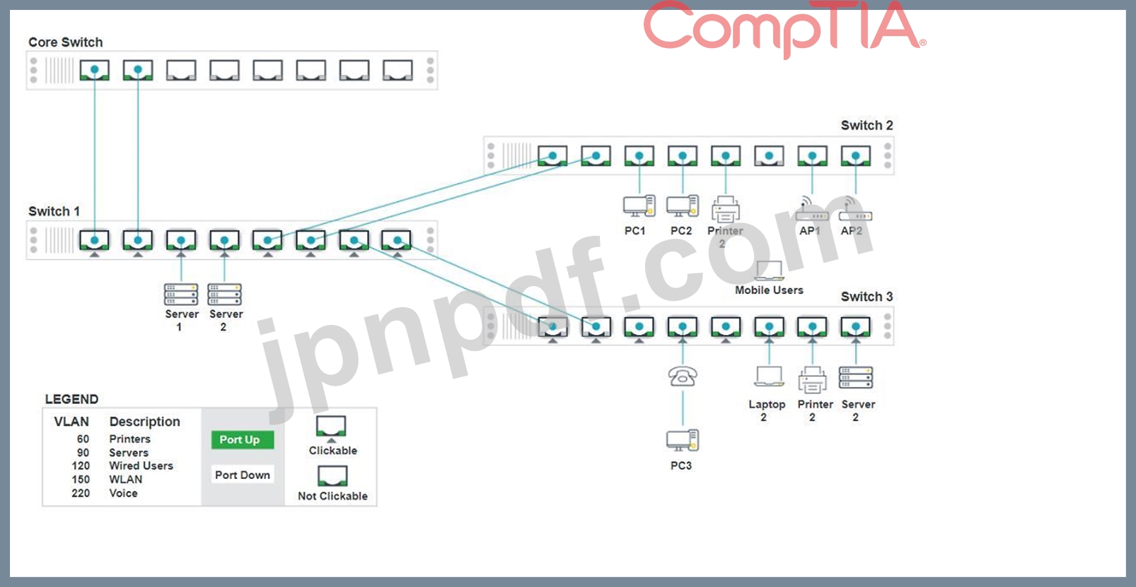
ネットワーク技術者がアクセス レイヤー スイッチを交換し、接続されたデバイスが正しいネットワークに接続できるように再構成する必要があります。
説明書
スイッチ 1 とスイッチ 3 の適切なポートをクリックして、正しい設定を確認または再構成します。
各デバイスが特定のデバイスのみにアクセスできるように
正しく関連付けられたネットワーク。
未使用のスイッチポートをすべて無効にします。
フォールトトレラント接続を必要とする
スイッチ間。
必要な変更のみ行ってください
上記の要件を完了してください。
説明書
スイッチ 1 とスイッチ 3 の適切なポートをクリックして、正しい設定を確認または再構成します。
各デバイスが特定のデバイスのみにアクセスできるように
正しく関連付けられたネットワーク。
未使用のスイッチポートをすべて無効にします。
フォールトトレラント接続を必要とする
スイッチ間。
必要な変更のみ行ってください
上記の要件を完了してください。
正解:
See the solution below in Explanation.
Explanation:
To provide a complete solution for configuring the access layer switches, let's proceed with the following steps:
* Identify the correct VLANs for each device and port.
* Enable necessary ports and disable unused ports.
* Configure fault-tolerant connections between the switches.
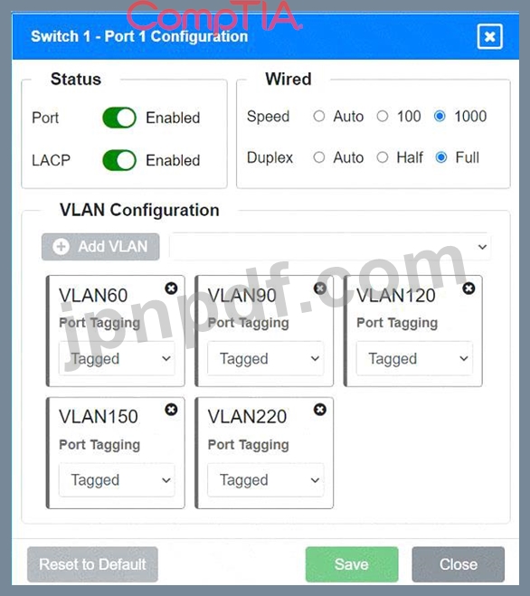
Port 1 Configuration (Uplink to Core Switch)
* Status: Enabled
* LACP: Enabled
* Speed: 1000
* Duplex: Full
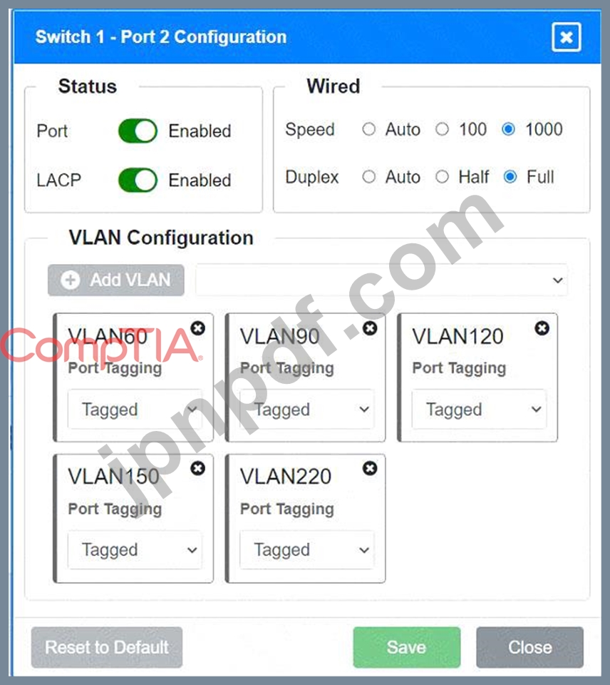
* VLAN Configuration: Tagged for VLAN60, VLAN90, VLAN120, VLAN150, VLAN220 Port 2 Configuration (Uplink to Core Switch)
* Status: Enabled
* LACP: Enabled
* Speed: 1000
* Duplex: Full
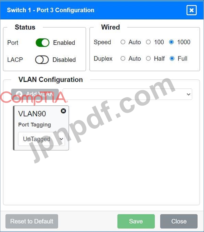
* VLAN Configuration: Tagged for VLAN60, VLAN90, VLAN120, VLAN150, VLAN220 Port 3 Configuration (Server Connection)
* Status: Enabled
* LACP: Disabled
* Speed: 1000
* Duplex: Full
* VLAN Configuration: Untagged for VLAN90 (Servers)
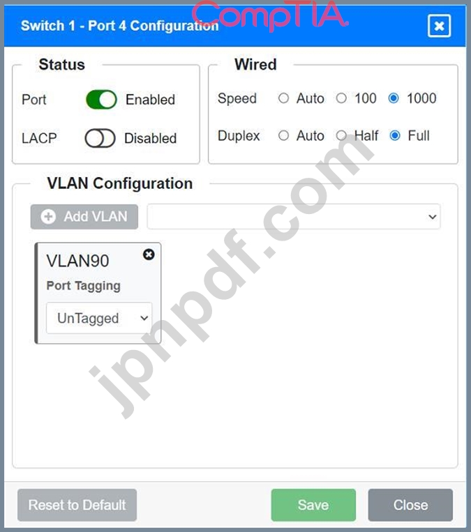
Port 4 Configuration (Server Connection)
* Status: Enabled
* LACP: Disabled
* Speed: 1000
* Duplex: Full
* VLAN Configuration: Untagged for VLAN90 (Servers)
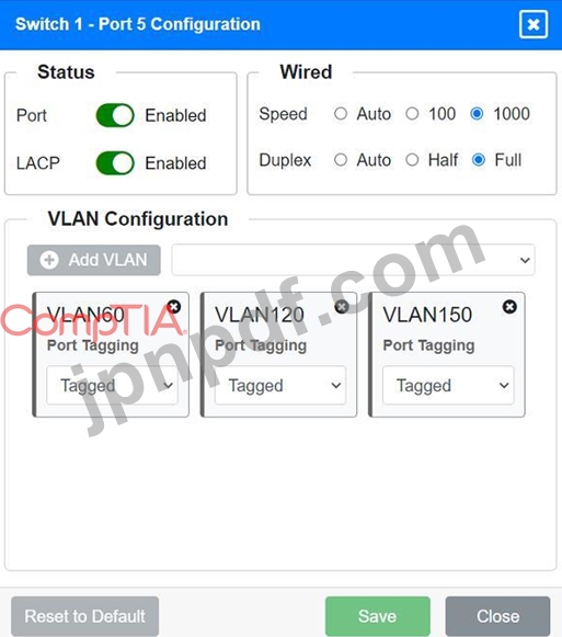
Port 5 Configuration (Wired Users and WLAN)
* Status: Enabled
* LACP: Enabled
* Speed: 1000
* Duplex: Full
* VLAN Configuration: Tagged for VLAN60, VLAN120, VLAN150
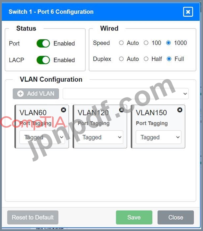
Port 6 Configuration (Wired Users and WLAN)
* Status: Enabled
* LACP: Enabled
* Speed: 1000
* Duplex: Full
* VLAN Configuration: Tagged for VLAN60, VLAN120, VLAN150
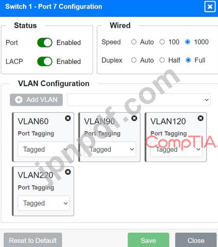
Port 7 Configuration (Voice and Wired Users)
* Status: Enabled
* LACP: Enabled
* Speed: 1000
* Duplex: Full
* VLAN Configuration: Tagged for VLAN60, VLAN90, VLAN120, VLAN220
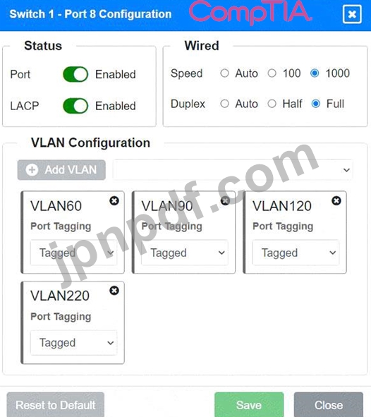
Port 8 Configuration (Voice, Printers, and Wired Users)
* Status: Enabled
* LACP: Enabled
* Speed: 1000
* Duplex: Full
* VLAN Configuration: Tagged for VLAN60, VLAN90, VLAN120, VLAN220
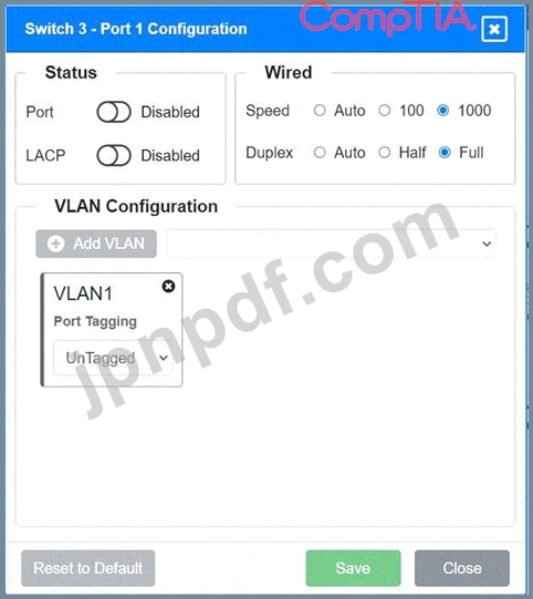
Port 1 Configuration (Unused)
* Status: Disabled
* LACP: Disabled
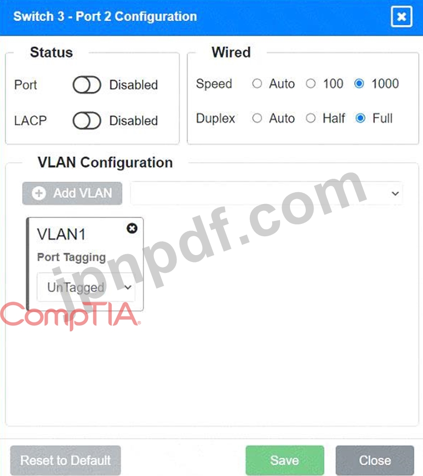
Port 2 Configuration (Unused)
* Status: Disabled
* LACP: Disabled
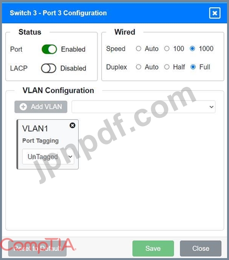
Port 3 Configuration (Connection to Device)
* Status: Enabled
* LACP: Disabled
* Speed: 1000
* Duplex: Full
* VLAN Configuration: Untagged for VLAN1 (Default)
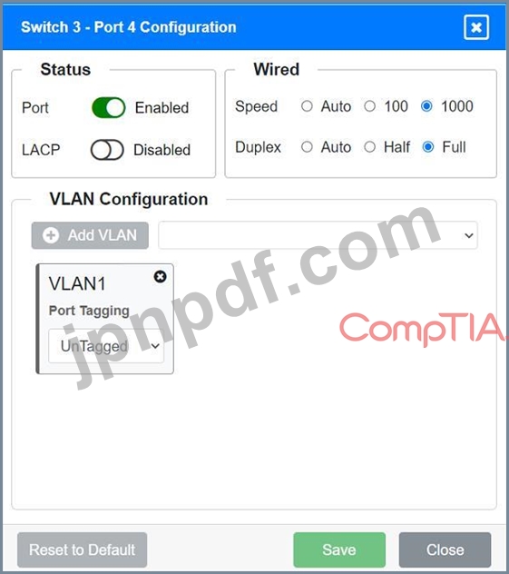
Port 4 Configuration (Connection to Device)
* Status: Enabled
* LACP: Disabled
* Speed: 1000
* Duplex: Full
* VLAN Configuration: Untagged for VLAN1 (Default)
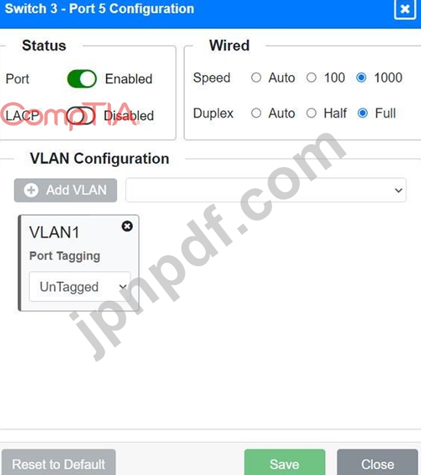
Port 5 Configuration (Connection to Device)
* Status: Enabled
* LACP: Disabled
* Speed: 1000
* Duplex: Full
* VLAN Configuration: Untagged for VLAN1 (Default)
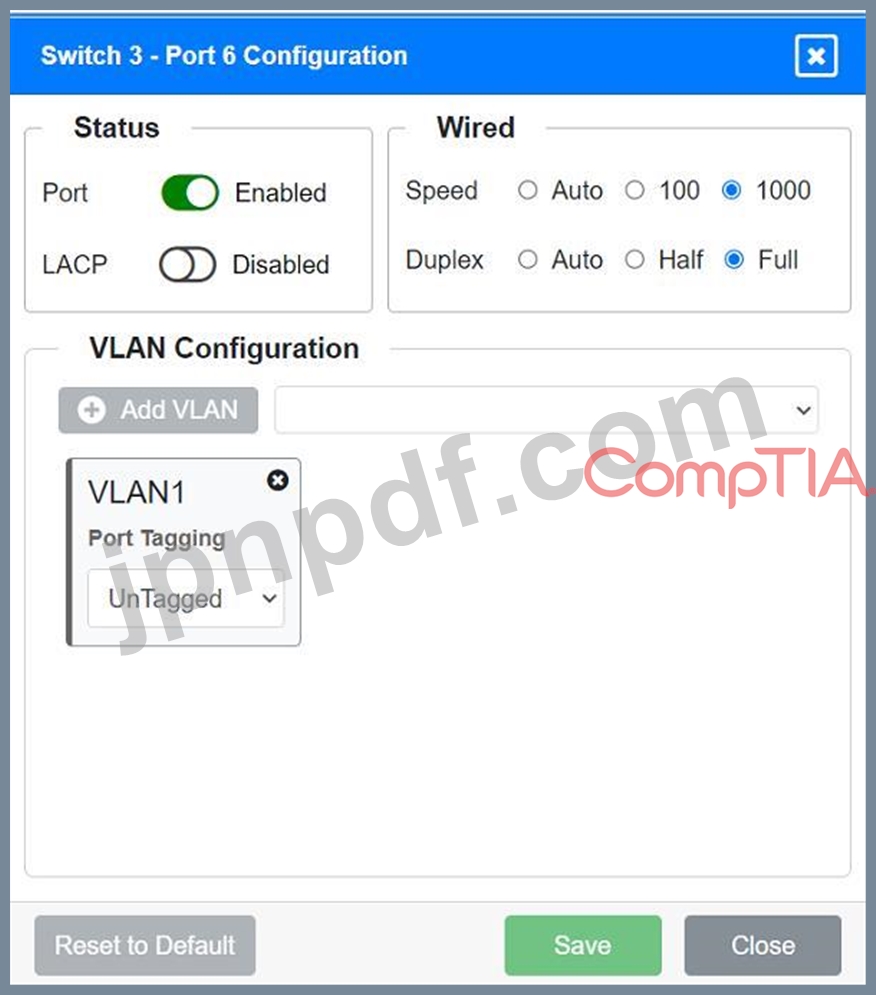
Port 6 Configuration (Connection to Device)
* Status: Enabled
* LACP: Disabled
* Speed: 1000
* Duplex: Full
* VLAN Configuration: Untagged for VLAN1 (Default)
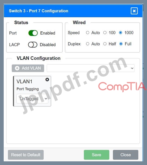
Port 7 Configuration (Connection to Device)
* Status: Enabled
* LACP: Disabled
* Speed: 1000
* Duplex: Full
* VLAN Configuration: Untagged for VLAN1 (Default)
* Ports 1 and 2 on Switch 1 are configured as trunk ports with VLAN tagging enabled for all necessary VLANs.
* Ports 3 and 4 on Switch 1 are configured for server connections with VLAN 90 untagged.
* Ports 5, 6, 7, and 8 on Switch 1 are configured for devices needing access to multiple VLANs.
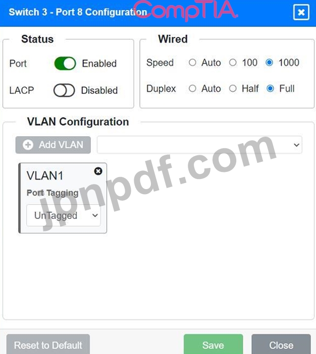
* Unused ports on Switch 3 are disabled.
* Ports 3, 4, 5, 6, and 7 on Switch 3 are enabled for default VLAN1.
* Core Switch Ports should be configured as needed for uplinks to Switch 1.
* Ensure LACP is enabled for redundancy on trunk ports between switches.
By following these configurations, each device will access only its correctly associated network, unused switch ports will be disabled, and fault-tolerant connections will be established between the switches.
Explanation:
To provide a complete solution for configuring the access layer switches, let's proceed with the following steps:
* Identify the correct VLANs for each device and port.
* Enable necessary ports and disable unused ports.
* Configure fault-tolerant connections between the switches.
Port 1 Configuration (Uplink to Core Switch)
* Status: Enabled
* LACP: Enabled
* Speed: 1000
* Duplex: Full
* VLAN Configuration: Tagged for VLAN60, VLAN90, VLAN120, VLAN150, VLAN220 Port 2 Configuration (Uplink to Core Switch)
* Status: Enabled
* LACP: Enabled
* Speed: 1000
* Duplex: Full
* VLAN Configuration: Tagged for VLAN60, VLAN90, VLAN120, VLAN150, VLAN220 Port 3 Configuration (Server Connection)
* Status: Enabled
* LACP: Disabled
* Speed: 1000
* Duplex: Full
* VLAN Configuration: Untagged for VLAN90 (Servers)
Port 4 Configuration (Server Connection)
* Status: Enabled
* LACP: Disabled
* Speed: 1000
* Duplex: Full
* VLAN Configuration: Untagged for VLAN90 (Servers)
Port 5 Configuration (Wired Users and WLAN)
* Status: Enabled
* LACP: Enabled
* Speed: 1000
* Duplex: Full
* VLAN Configuration: Tagged for VLAN60, VLAN120, VLAN150
Port 6 Configuration (Wired Users and WLAN)
* Status: Enabled
* LACP: Enabled
* Speed: 1000
* Duplex: Full
* VLAN Configuration: Tagged for VLAN60, VLAN120, VLAN150
Port 7 Configuration (Voice and Wired Users)
* Status: Enabled
* LACP: Enabled
* Speed: 1000
* Duplex: Full
* VLAN Configuration: Tagged for VLAN60, VLAN90, VLAN120, VLAN220
Port 8 Configuration (Voice, Printers, and Wired Users)
* Status: Enabled
* LACP: Enabled
* Speed: 1000
* Duplex: Full
* VLAN Configuration: Tagged for VLAN60, VLAN90, VLAN120, VLAN220
Port 1 Configuration (Unused)
* Status: Disabled
* LACP: Disabled
Port 2 Configuration (Unused)
* Status: Disabled
* LACP: Disabled
Port 3 Configuration (Connection to Device)
* Status: Enabled
* LACP: Disabled
* Speed: 1000
* Duplex: Full
* VLAN Configuration: Untagged for VLAN1 (Default)
Port 4 Configuration (Connection to Device)
* Status: Enabled
* LACP: Disabled
* Speed: 1000
* Duplex: Full
* VLAN Configuration: Untagged for VLAN1 (Default)
Port 5 Configuration (Connection to Device)
* Status: Enabled
* LACP: Disabled
* Speed: 1000
* Duplex: Full
* VLAN Configuration: Untagged for VLAN1 (Default)
Port 6 Configuration (Connection to Device)
* Status: Enabled
* LACP: Disabled
* Speed: 1000
* Duplex: Full
* VLAN Configuration: Untagged for VLAN1 (Default)
Port 7 Configuration (Connection to Device)
* Status: Enabled
* LACP: Disabled
* Speed: 1000
* Duplex: Full
* VLAN Configuration: Untagged for VLAN1 (Default)
* Ports 1 and 2 on Switch 1 are configured as trunk ports with VLAN tagging enabled for all necessary VLANs.
* Ports 3 and 4 on Switch 1 are configured for server connections with VLAN 90 untagged.
* Ports 5, 6, 7, and 8 on Switch 1 are configured for devices needing access to multiple VLANs.
* Unused ports on Switch 3 are disabled.
* Ports 3, 4, 5, 6, and 7 on Switch 3 are enabled for default VLAN1.
* Core Switch Ports should be configured as needed for uplinks to Switch 1.
* Ensure LACP is enabled for redundancy on trunk ports between switches.
By following these configurations, each device will access only its correctly associated network, unused switch ports will be disabled, and fault-tolerant connections will be established between the switches.
- 他のバージョン
- 1515CompTIA.N10-009J.v2025-07-01.q101
- 594CompTIA.N10-009J.v2025-06-20.q81
- 614CompTIA.N10-009J.v2025-06-18.q85
- 最新アップロード
- 103Oracle.1z0-1057-25.v2026-06-04.q45
- 104Amazon.AWS-Certified-Developer-Associate.v2026-06-04.q323
- 106Fortinet.FCSS_SDW_AR-7.4.v2026-06-04.q76
- 130SAP.C_THR88_2505.v2026-06-03.q76
- 137WGU.Web-Development-Applications.v2026-06-03.q73
- 130Salesforce.Mule-Dev-301.v2026-06-02.q22
- 181CISI.IFC.v2026-06-02.q111
- 188Huawei.H13-611_V5.0.v2026-06-01.q113
- 222Cisco.200-201.v2026-06-01.q230
- 184Huawei.H35-211_V2.5.v2026-06-01.q109